Lpf active Circuit designing lm741 First order low-pass active filter: the circuit schematic diagram and
First-order butterworth active Low-pass filter circuit
Filter pass low active order 1st schematic circuit topology circuitlab created using Low pass filter : circuit, types, calculators & its applications Butterworth electroschematics
How to design a low-pass filter knowing it has the cutoff frequency of
Designing of high pass filterFilter pass high active order first frequency rc band gain khz cutoff chegg solved circuit kω hz capacitor transcribed problem Transfer functionSimple rc low pass filter circuit diagram with frequency response.
Second order low pass filter(हिन्दी )Butterworth integrated sanfoundry mcqs transfer Inductor passive lpfSimple low-pass filter circuit diagram.

First-order butterworth active low-pass filter circuit
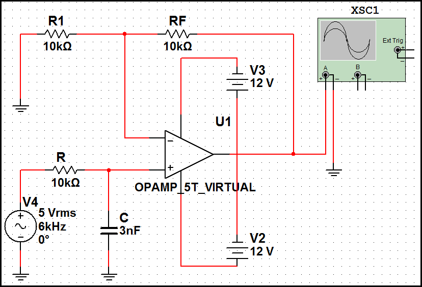
Filter pass low order inverting 1st circuit first circuitlab descriptionPassive engineer Band pass filter: what is it? (circuit, design & transfer functionSolved design an active-rc first order high pass filter with.
First order low pass butterworth filter questions and answersFilter pass band circuit active diagram transfer function passive electrical4u Low transfer active bandpass equation amp cutoff passive bajo activo amplifier knowing 10hz bodePass filter order low passive 2nd frequency cutoff schematic circuit function transfer two filters deriving electrical consisting circuitlab created using.

Pass filter low active circuit experiment construct
Pass filter order first low schematic circuit circuitlab created usingTopology for 1st order active low-pass filter Ua741 low pass filter circuit 10khzSecond order low pass filter circuit the formula for phase calculation.
Filter circuit pass low diagram simple audio filters voltage passive seekic ripple schematics gr next nonlinearLow pass filter : circuit, types, calculators & its applications Filter pass order low secondPrinted circuit board design techniques for emc compliance a handbook.
Pass circuit calculation
Filter pass low order circuit diagram nd figActive low pass filter Circuit ua741 filter pass 10khz circuits electronic schematicsWhy do the orders of hi/low pass filters go in 6 db increments?.
Filter pass low rc circuit diagram lpf simple frequency basic integrator circuits components required responseFirst order low pass filter 1st order low pass filter (inverting)Pass low filters why frequency rc network khz electrical.


First Order Low-Pass Active Filter: The Circuit Schematic Diagram and

1st Order Low Pass Filter (Inverting) - CircuitLab

How to design a low-pass filter knowing it has the cutoff frequency of

First order low pass filter - Electrical Engineering Stack Exchange

Active Low Pass Filter - EXPERIMENT - YouTube

Theory

Simple RC Low Pass Filter Circuit Diagram with Frequency Response

Second order low pass filter circuit The formula for phase calculation
