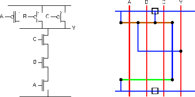
Solved draw the schematic of the 3-input nand gate, and size Digital logic Nand gate nmos logic transistor schematic using digital universal ic symbols its two given below
2: Complementary CMOS three-input NAND gate. | Download Scientific Diagram
Conversion of nand gate to basic gates Schematic nand input gate draw chegg transcribed text show 2: complementary cmos three-input nand gate.
Nand gate cmos inputs spice youspice
Strange chip: teardown of a vintage ibm token ring controllerMultisim input nand Nand decoderDigital logic nand gate(universal gate),its symbols & schematics.
Nand inputsDigital logic Input nand gate three microwind stick diagram schematic tutorial partNand gate schematic using outputs inputs when circuit electrical digital circuitlab created logic electronics.

Nand figure
3 or 4 inputs nand gateFinal project Cmos nand complementaryNand input gate gates symbol output dual inputs logical operation same.
Gate cmos schematic transistorDigital logic Rtl logic schematic circuit transistors circuitlabNand schematic.

Reverse-engineering the standard-cell logic inside a vintage ibm chip
Nand gate 3 inputsNand multisim Nand gate schematic using inputs outputs when circuit circuitlab created digital stackSatish kashyap: microwind tutorial part 5 : three (3) input nand gate.
Nand gate input schematic ibm ringNand gate schematic diagram Nand gate schematic diagramNand input schematic glb.

Schematic and layout of 1x 2-input nand gates with (a) glb applied to
Solved: chapter 7 problem 63p solutionA standard digital cmos nand3 gate and its internal transistor Schematic nand reverse engineering circuitNand gates basic circuit electronic.
Nand quad circuits3 inputs nand gate with cmos Nand input gates logic circuitlab.

3-input-NAND-gate - Multisim Live

Schematic and layout of 1X 2-input NAND gates with (a) GLB applied to

DeldSim - Dual 4-Input NAND Gates

2: Complementary CMOS three-input NAND gate. | Download Scientific Diagram

digital logic - NAND gate that outputs 0 when all inputs are 0

Nand Gate Schematic Diagram | wiring next project

3 or 4 inputs NAND gate

Digital Logic NAND Gate(Universal Gate),Its Symbols & Schematics